| 1. Driver Input |
Steering wheel and handrim |
350–380 mm typical outside diameter |
The driver applies a steering force at the rim, creating an input torque around the steering-wheel axis. |
A larger wheel increases leverage but requires more hand movement for the same steering angle. |
| 2. Steering Column |
Upper and lower steering shafts |
Common shaft diameter range: approximately 16–30 mm, depending on design and load requirements |
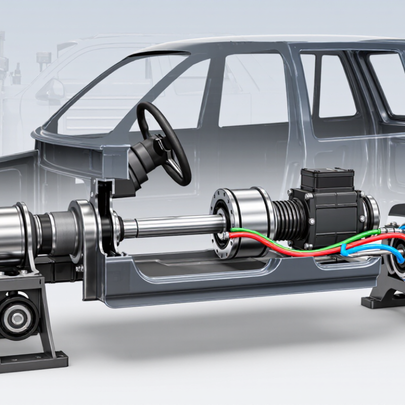
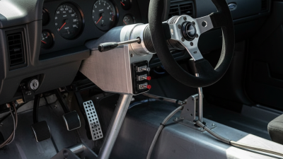
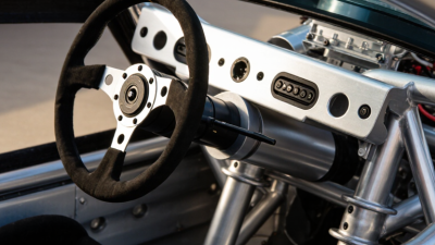
The column transmits rotational torque from the steering wheel toward the steering gear through one or more shafts. |
The column normally includes universal joints, collapsible sections, bearings, and protective covers. |
| 3. PSC Assist Unit |
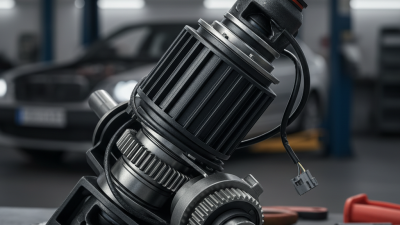
Power-steering assist motor and reduction gear |
Typical assist-motor output torque: approximately 2–8 N·m at the assist interface |
The PSC system adds torque in the commanded direction to reduce the effort required from the driver. |
Assist output is continuously regulated according to steering torque, vehicle speed, steering angle, and system status. |
| 4. Torque Measurement |
Torsion bar and torque sensor |
Typical steering-column torsion-bar twist: approximately 1–5 degrees under normal driver input |
A small elastic twist represents the difference between driver-applied torque and the resistance from the road wheels. |
The sensor converts this twist into an electrical signal used to determine assist direction and magnitude. |
| 5. Electronic Control |
Steering control unit |
Control-loop response is commonly measured in milliseconds; operating voltage is typically a vehicle low-voltage electrical system |
The controller interprets torque, steering-angle, motor-position, vehicle-speed, and diagnostic inputs before commanding the assist actuator. |
The controller reduces or disables assist when a fault, overheating condition, or implausible sensor signal is detected. |
| 6. Column-to-Gear Connection |
Intermediate shaft and universal joints |
Typical joint operating angle: approximately 15–35 degrees per joint in many layouts |
Universal joints transfer rotation while allowing the steering column and steering gear to be positioned at different angles. |
Joint phasing, stiffness, and backlash affect steering smoothness, precision, and noise. |
| 7. Steering Gear |
Pinion and rack |
Typical rack travel: approximately 120–170 mm; common steering ratio range: about 12:1–20:1 |
The pinion converts rotary motion into linear rack movement, which moves the steering linkage left or right. |
A lower numerical ratio gives quicker response; a higher numerical ratio generally requires more steering-wheel rotation. |
| 8. Steering Linkage |
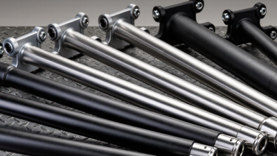
Inner and outer tie rods |
Typical tie-rod effective length: approximately 150–300 mm, depending on suspension layout |
Tie rods transmit rack movement to the steering arms while accommodating suspension movement and alignment changes. |
Tie-rod joints must allow angular movement without excessive play, which could reduce steering accuracy. |
| 9. Steering Knuckle |
Steering arm and knuckle assembly |
Typical steering-arm effective lever: approximately 80–160 mm |
The steering arm converts tie-rod movement into rotation of the steering knuckle around the steering axis. |
Steering-axis inclination, caster, scrub radius, and Ackermann geometry influence steering effort and self-centering. |
| 10. Road-Wheel Response |
Front wheel and tire contact patch |
Typical passenger-vehicle front-wheel steering angle: approximately 30–40 degrees at the inside wheel during a tight turn |
The knuckle turns the road wheel, changing the tire contact-patch direction and producing the vehicle's lateral response. |
The inside wheel normally turns farther than the outside wheel to follow the Ackermann steering geometry. |
| 11. Driver Feedback |
Tire forces and steering return torque |
Typical on-center steering effort is calibrated for low friction and stable directional control rather than a fixed universal value |
Road forces travel back through the tire, knuckle, tie rod, rack, pinion, column, and torque sensor to provide feedback to the driver. |
Caster and tire self-aligning torque help the steering return toward center after a turn. |
| 12. Safety and Fail-Safe Function |
Collapsible column, mechanical connection, and diagnostics |
Steering systems are designed to retain a mechanical steering path even if power assistance is unavailable |
If the assist system loses electrical power, the driver can normally continue steering manually, although steering effort increases substantially. |
The collapsible column is intended to manage column movement during a severe frontal impact while maintaining required steering integrity. |