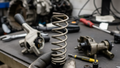
What Is Peterbilt Tilt Steering Column Parts?
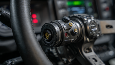
A Peterbilt tilt steering column is more than a driver comfort feature. It is a safety-related assembly that connects steering input with the vehicle’s steering gear. The phrase “peterbilt tilt steering column parts” may include the tilt mechanism, pivot pins, bearings, locking lever, steering shaft, wiring connectors, ignition components, and protective covers. Each part must match the truck’s model year and column design. A 379 column may not accept parts from a 389 column without careful verification.
Industry data shows why this subject matters. The American Trucking Associations’ American Trucking Trends 2024 reported that trucks carry roughly 72.6% of domestic freight by weight in the United States. These vehicles operate for long hours, often under vibration, heat, and repeated steering movement. ACT Research also continues to track strong North American Class 8 truck production and replacement demand. That activity increases the need for dependable steering-column inspection and parts identification. Small wear can become a serious operating concern.
Look closely at the tilt joint.
A loose lever, uneven movement, damaged spline, or clicking sound deserves attention. Experienced technicians usually compare the part number, column height, wiring layout, and mounting pattern before ordering. The Federal Motor Carrier Safety Administration emphasizes proper inspection and maintenance of commercial vehicles, reinforcing the need for documented repair decisions. Still, part catalogs are not perfect. I have seen similar-looking components create installation problems. That assumption is convenient, but not always correct. This guide explains the main peterbilt tilt steering column parts, their functions, common failure signs, and practical selection considerations.
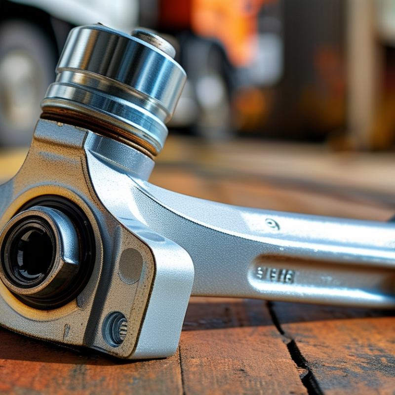
Definition and Purpose of Peterbilt Tilt Steering Column Parts
Tilt Steering Column Parts: Definition and Purpose
Tilt steering column parts are the components that let a driver adjust the steering wheel angle. They also keep the wheel stable during operation. Common parts include the tilt mechanism, pivot pins, locking lever, return spring, bearings, and steering shaft connections. Some columns also contain wiring contacts for the horn and other controls.
The main purpose is control, comfort, and safe steering response. A locking lever releases the column for adjustment. When released, the wheel can move upward or downward. When locked, internal teeth or a clamping system hold the selected position. Pivot pins guide movement, while bearings reduce friction. The steering shaft transfers driver input to the steering gear without unwanted delay.
Small wear can create serious symptoms. A loose wheel may indicate worn pivot points or a weak locking mechanism. Clicking sounds can suggest damaged teeth or dry contact surfaces. In repair work, technicians should inspect movement before replacing parts. Measurements matter. Shaft size, spline design, mounting points, and electrical connections must match the original assembly.
The fit is not always perfect. Even a new part may need careful alignment. Over-tightening fasteners can restrict tilt movement. Under-tightening can create dangerous looseness. After installation, check the full tilt range, steering return, and control wiring. A short road test on a safe route can reveal problems missed in the workshop. Never ignore a minor wobble.
Main Components of a Peterbilt Tilt Steering Column
What Is a Heavy-Duty Tilt Steering Column?
A tilt steering column connects the steering wheel to the steering gear while allowing angle adjustment. Its main components work together under constant vibration, heat, and driver movement. The steering wheel hub transfers hand input to the upper steering shaft. Inside the column, bearings support smooth rotation and reduce side movement. Pivot pins and a tilt bracket control the column’s angle. A release lever unlocks the mechanism, while a locking plate holds the selected position. Small parts matter here. A worn spring or loose fastener can affect the entire assembly.
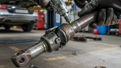
The lower shaft, intermediate shaft, and universal joints carry rotation toward the steering gear. Some columns also include an ignition housing, wiring contacts, and protective covers. During inspection, check for excessive wheel play, uneven resistance, cracked plastic, and clicking near the pivot area. The tilt lever should move firmly, not loosely.
Do not guess torque values; use the vehicle service manual and approved tools. A common mistake is replacing the column before checking the universal joints. Another is adding grease without confirming the correct lubricant. Too much lubricant can attract dust. That detail is easy to miss. Careful measurement remains more reliable than appearance alone. Even experienced technicians can overlook a slightly bent shaft after a minor impact. Record the symptoms before disassembly, and compare each removed part with its replacement.
How Peterbilt Tilt Steering Column Parts Work Together
A tilt steering column is a coordinated system, not a single tube. The steering wheel connects to an upper shaft inside the column. Bearings support this shaft and help it rotate smoothly. A lower shaft then transfers movement toward the steering gearbox or steering rack.
The tilt housing allows the wheel angle to change for driver comfort. Pivot pins guide this movement. A locking lever clamps the housing firmly after adjustment. When the lever is released, spring tension and the pivot points permit controlled movement. Electrical wires may pass through the column for the horn, indicators, or other controls. These parts must move without pulling, rubbing, or bending the wiring. In workshop inspections, I have found that minor looseness is often blamed on the shaft. The real cause may be worn pivot pins or a weak locking mechanism. That detail is easy to miss.
Tips: Check wheel play with the vehicle safely parked. Move the wheel gently up and down. Listen for clicking sounds. Inspect the locking lever, pivot area, and exposed wiring. Do not force a stiff mechanism. A qualified technician should measure shaft movement and verify fastener torque. Replacement parts must match the column design and load requirements. Even a clean-looking assembly can hide internal wear. Regular inspection is wiser than waiting for steering response to feel unusual.
What Is Peterbilt Tilt Steering Column Parts? - How Peterbilt Tilt Steering Column Parts Work Together
| Part or Assembly | Primary Function | How It Works With Other Parts | Typical Material or Design | Common Wear or Failure Sign |
|---|---|---|---|---|
| Steering Wheel | Provides the driver interface for turning the vehicle. | Transfers driver input to the steering shaft through the wheel hub and retaining hardware. | Usually a steel hub with a polymer or elastomer-covered rim. | Loose mounting, excessive movement, damaged rim, or unusual steering-wheel vibration. |
| Tilt Release Lever | Allows the driver to unlock the steering column angle for adjustment. | Operates a linkage connected to the tilt lock mechanism; releasing the lever permits controlled movement. | Stamped or machined metal lever with a pivot and return spring. | Lever feels loose, does not return, or the column will not lock securely. |
| Tilt Lock Mechanism | Holds the column at the selected tilt position during driving. | Uses a locking plate, teeth, pins, or friction surfaces that engage when the release lever is returned. | Hardened steel locking components with a spring-loaded engagement system. | Column moves under load, fails to hold position, or produces clicking during adjustment. |
| Upper Steering Shaft | Carries rotational input from the steering wheel toward the lower shaft. | Connects through splines, a coupler, or a telescoping interface to accommodate column movement and alignment. | Precision-machined steel shaft, often with splined ends. | Excessive play, binding, corrosion, or a clunk when the wheel changes direction. |
| Lower Steering Shaft and Coupler | Transfers torque from the column to the steering gear or steering assist unit. | Uses a flexible or articulated coupling to accommodate chassis movement and changes in shaft angle. | Steel shaft with a mechanical coupler, universal joint, or flexible disc assembly. | Stiff steering, looseness, rust, damaged coupling material, or visible joint wear. |
| Column Housing | Supports the steering shaft, bearings, switches, and tilt components. | Provides the fixed and movable structure required for shaft alignment and tilt adjustment. | Cast or formed metal housing with protective trim components. | Cracks, distorted mounting points, rattling trim, or misalignment of the steering shaft. |
| Bearings and Bushings | Support the steering shaft while allowing smooth rotation and limiting radial movement. | Maintain shaft alignment inside the housing and work with the tilt mechanism during column movement. | Steel bearings and engineered polymer or bronze bushings, depending on location. | Rough rotation, steering-wheel wobble, squeaking, or increased shaft clearance. |
| Mounting Bracket | Secures the steering column to the cab or instrument-panel support structure. | Provides the stationary reference point from which the tilt section pivots or locks. | Heavy-gauge formed or cast steel with bolted mounting points. | Loose fasteners, cracked brackets, column vibration, or movement at the dash area. |
| Return Springs | Return the release lever and locking components to the engaged position. | Work with the tilt lock so the column re-engages after the driver selects an angle. | Coiled or torsion springs made from spring steel. | Slow lever return, incomplete locking, or a release lever that remains partially open. |
| Electrical Switch Module | Controls or supports functions such as turn signals, horn, wipers, or other steering-column electrical circuits. | Receives mechanical input from the steering wheel or switch stalk while wiring routes signals to vehicle systems. | Plastic electrical housing with copper contacts, terminals, and insulated wiring. | Intermittent signals, horn failure, non-canceling indicators, or damaged wiring. |
| Retaining Nut, Bolt, and Fasteners | Secure the steering wheel, column housing, brackets, and adjustment components. | Maintain clamping force so torque can pass through the shaft without unwanted movement. | High-strength steel hardware, often with locking features. | Looseness, damaged threads, missing locking hardware, or movement after tightening. |
Common Problems and Signs of Component Failure
Tilt Steering Column Parts: Common Problems and Signs of Component Failure
A tilt steering column allows drivers to adjust wheel height for comfort and control. Its main parts include the pivot pins, locking mechanism, tilt spring, bearings, shaft, and electrical connectors. Each component works under vibration, heat, and frequent movement. Small wear can become noticeable during daily driving.
A loose steering wheel is a serious warning sign. It may move upward or downward after the lever is locked. The locking mechanism could be worn, damaged, or poorly adjusted. Grinding sounds often point to dry bearings or worn pivot areas. A stiff tilt lever may indicate corrosion, a weak spring, or debris inside the housing. Do not force it. That can damage nearby parts.
Electrical problems can appear around the column as well. Turn signals, horn controls, or other switches may work intermittently. A damaged connector or clock spring can interrupt those circuits. The wheel may also feel uneven when turning.
In my experience, drivers sometimes blame the steering gear too quickly. The actual fault can be a simple loose fastener or worn bearing. Diagnosis should include a visual inspection, movement test, and fastener check. Always secure the vehicle before testing. I have seen symptoms change after temperature shifts, so one short inspection may not reveal everything. If play, cracking, or sudden stiffness appears, professional evaluation is the safer choice.
Inspection, Replacement, and Maintenance Guidelines
A tilt steering column contains more than a wheel hinge. Common parts include the tilt lever, pivot pins, locking mechanism, upper and lower bearings, steering shaft, wiring, and mounting hardware. During inspection, park on level ground and disconnect the battery before touching electrical components. Move the wheel through every tilt position. It should lock firmly without clicking, slipping, or requiring excessive force.
Check for radial play, uneven resistance, damaged splines, loose brackets, and wiring that stretches during adjustment. A small amount of movement can become serious under repeated cab vibration. The Commercial Vehicle Safety Alliance reported 48,761 commercial vehicles inspected during the 2024 International Roadcheck, with 23.3% placed out of service. That figure covers many systems, not steering columns specifically, but it shows why small defects deserve attention.
Replacement requires careful identification of the column design and shaft connection. Record the original wheel position, mark shaft alignment, and use calibrated tools for fastener torque. Never guess torque values. Follow the applicable service manual. After installation, confirm horn, turn signals, canceling function, and wheel lock operation. A road test should begin at low speed in a controlled area.
Maintenance is often simple. Keep the tilt mechanism clean, inspect mounting bolts during scheduled service, and apply only the lubricant specified for the assembly. Grease is not always helpful. I have seen excess lubricant attract grit and create a rougher mechanism. That mistake is easy to repeat. If the column binds, shifts, or fails to lock, remove the vehicle from service until a qualified technician evaluates it.
Related Posts
-
Understanding GM Column Shifter Spring How It Affects Performance?
-
How to Replace F100 Steering Column Parts Easily?
-

Essential Tips for Choosing Motor Housings for Your Needs?
-
How to Find Peterbilt Tilt Steering Column Parts Easily?
-
Why Upgrading to PSC Steering Box Duramax Enhances Your Vehicle's Performance
-
10 Essential Tips for Maintaining Your Steering Shaft Knuckle?